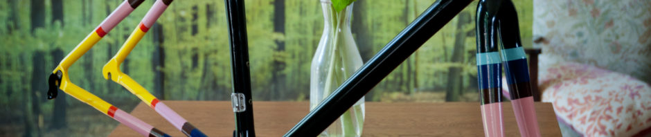
A while back my awesome LBS gave me a box of carbon tubes and lugs and said “You’re the right person to give these too!”. And with that I had 4 frames to build, one of which I’ve completed. Take a squizz:
The process wasn’t a simple one. Here’s what I did:
Bonded all carbon tubes and dropouts together
Sanded and filed those back.
Drilled and riveted front derailleur clamp
Drilled and set water bottle bosses
Drilled custom internal cable routing
3D printed custom rear brake boss
3D printed cable stop for front derailleur cable
Masked and handpainted the colour stripes with enamel paint
Flat black enamel spray followed by 3 coats of gloss enamel spray.
What does this mean for bamboo? Well, I don’t know at this stage. It’s certainly easier working with full carbon, pre-made tubes! Maybe there’ll be another bamboo bike made soon… only time will tell.
So I’ve been bunkering down in the Melbourne winter in front of 3D CAD programs designing various parts for the next bamboo bike. My aim is to reduce the amount of manual labour in the manufacture of the bikes and increase their quality, but still allow for individual geometries and styles. There’s a guy on Instructables who’s made a Custom 3D printed carbon fibre and aluminium bike and a lot of what he’s done is the genesis of my ideas for how to go about making custom molds that could be used with bamboo. There’s also this guy who’s made an amazingly detailed frame using 3D printed stainless steel lugs and carbon fibre poles. The triangle cutouts in the lugs are no doubt to save weight – as with 3D printing the amount of material you use is the main cost, and there’s limits to how thin walls can be (~3mm). So thick and chunky but with lots of holes in it seems to be the way to go.
This all sounds well and good, but there’s some caveats. The material properties of 3D printed stainless steel are not necessarily the same as regular steel. It’s infused with brass as part of the process, which, along with the process used, makes it much more brittle than normal. Regular stainless steel has an elongation of around 23%. 3D printed steel only has 2.3%. That’s a huge difference. There’s other 3D printers (like the one the guy used in the video above) that claim different material properties that are closer to normal stainless, but by the looks they’re also very expensive. I’m hoping the material technology will get better in the next few years so that this won’t be an issue.
So far I’ve modelled and produced some cable-stops which are specifically designed for use with bamboo or carbon fibre frames. Here’s a close up pic of one made from plastic:
A close up of a 3D printed cable stop. The roughness is due to the manufacturing process, which uses extremely thing layers of plastic built up over each other and welded together by a laser.
What sets it apart from a regular cable-stop is the curvature on the bottom of it is designed for thicker tubing and the tabs on either side have holes ready for wood screws so it can bolt right on. It’d probably be fitted with a dab of epoxy as well to help it stick properly.
I’ve designed it to be usable for both gear and brake cables, but I’ll have to do some strength testing on its use for the latter as there’s a lot more force going through a brake cable than a gear cable.
If you’d like some for your own project the cable-stops are available to buy directly from Shapeways, the 3D printer I’ve used. Plastic ones are $7 a pop plus postage. Stainless steel is a fair bit more. I’ll soon be adding a double and triple stop for use along top-tubes.
I’ve also designed a head-tube badge and had it printed in both white and black. I’ve coloured in the lettering on the white one to make it stand out, and I’ll probably do the same on the black (white lettering no doubt).
Two 3D printed head-tube badges made from “strong but flexible” plastic.
The next step is to start to model a set of lugs themselves. I want to be able to design them in such a way that the geometry can be changed easily and a new model produced from the changes in geometry semi-automatically. It’s a big ask, and there’s a lot of work involved, but stay tuned and it might just happen.
The Samurai, my fourth frame was going well until I discovered that the seat-tube had developed some cracks around both the bottom bracket and where the seat-post sleeve inserts into it.
Luckily I hadn’t yet carbon fibered up either of those joints so I’ve been able to cut out the offending tube and will replace it with one that’s hopefully not so prone to cracking.
The cause of the cracking is probably due to the consistent cold temperates in the workshop overnight and that without coatings of epoxy bamboo will naturally dry out and become brittle and crack. It’s also due to the steel seat-post sleeve insert changing temperatures at different rates to the bamboo, causing the bamboo to crack.
Interestingly both the cracks were in places that would have been covered with carbon fiber and they probably won’t have propagated any further, but I couldn’t take the risk of that not being the case and don’t want to let a mistake roll out the door.
Below are some pics of the cracked seat-tube both before and after I’ve cut it out. It was interesting to see the different levels of adhesion (or lack thereof) of the epoxy to the various materials. It’s mostly only mechanically bonded to both the steel and the bamboo, making it very important to roughen up the surfaces to ensure a good bond. The aluminium bottom bracket is painted in a specific etch primer (the white paint), but it doesn’t seem to have chemically adhered properly to it. I’ll have to investigate why!
Bamboo Bike #3, dubbed The Panda by its eventual owner is nearing completion. I’ve laid up 95% of the carbon fibre and just need to do some final cosmetic layers and then lots of finishing. Then comes the tricky things like brake holes, derailleur mounts and cable stops. Then some clear coat, then some testing!
Bamboo Bike #4 isn’t far away either. The head-tube’s been wrapped and the rest is scheduled to be done next week.
Here’s a few progress pics of The Panda:
all layed up, just needs sanding back
still a few more layers to go, then lots of sanding
they’ll be polished up to a mirror finish
kinda went overboard on the filleting, but it should be super stiff
needs one more cosmetic layer and a bit more sanding
all done
looking pretty messy at this point with all the tape, but rest assured there’s beautifully scratch free bamboo under there!
The frame’s all done except for the top coats of epoxy resin. I’ve applied the first and it’s hanging up to dry. This will be sanded back and then 3 more coats applied. Check out the pics:
I’ve tried my hardest to make the carbon fibre as smooth as possible with this frame. It’s a balancing act between sanding back too much or leaving a few wrinkles. It’s painstaking work, and at some point you just have to stop and say, that’ll do – it is after all, a handmade frame and should have a few handmade qualities about it. I am, however, investigating new methods for the carbon-fibre layup that can decrease the time spent on the process.
I’m using expanding filler foam on this frame as lightweight way to make the joints more curvaceous (and thus stronger). It’s super easy to sand back and shape and doesn’t take long to set.
I’ve done the initial wrappings of the rear end and head-tube with 12K carbon fiber tow. So far it’s taken 90metres of the stuff! I’ll cover these in 1-3 layers of woven carbon fiber cloth then 2 layers of clear coat. Job done.
Above is a video of my homemade frame testing apparatus. It’s far from scientific, but good enough to satisfy my curiosity as to whether or not the frame passes the AS/NZS 1927:1998 Frame & Fork Assembly test. The method described for the test is as follows:
Method
(a) Anchor the rear wheel axle attachment points.
 (b) Apply a force of 890 N to the front axle attachment point towards and in line with the rear wheel axle and from the deflection reading compute the energy absorbed in joules.
 (c) Should the energy absorption reading at 890N be less than 40 J increase the force until this figure is attained.
 (d) Release the loading.
 (e) Examine the test specimen for any signs of fracture or permanent deformation. The examination shall include the fork steering tube. The examination for fractures shall be done at ×5 magnification.
 NOTE: This test applies equally to rigid and suspended frames. When testing a suspended frame the energy absorbed in reaching an applied force of 890 N can be expected to be substantially more than 40 J.
Theory
Based on my understanding of physics Joules are calculated by the formula: Work(Joules) = Force(N) x Distance(m). So to get the frame to absorb 40J of energy I have to make it move 45mm (40J = 890×0.045). So I set up my rig to shift the frame 45mm up from its resting position, then applied a force to the rear axle that pushed the frame forward by 45mm. The frame was blocked by the end of the rig thou so it couldn’t move, thus the force acts through the frame, causing the front forks to bend a lot!
Result
It seems to have passed the test. There was no cracking noises or breakages. I’ll pull apart the fork tonight and make sure the carbon steerer has survived and inspect the frame for cracks or deformations.
I’m continuing to wrap the bottom bracket joint today. I’ve now done a total of 9 layers, which I’m pretty sure will be enough for a sturdy and stiff BB.
After wrapping up each series of layers in cling wrap and PVC tape I place it inside my homemade autoclave. It gets up to 80 degrees C in there, with just a regular old hairdryer. 30-40minutes is all it needs at that temperature to cure the epoxy enough that the wrapping can be removed. It will continue to cure at room temperature over the next few days.
this is what happens when you forget to poke holes in the wrapping tape.
The headtube’s pretty much done so I’m now starting work on laying up the bottom bracket area. It’s a much more complex shape to work with, which made the template cutting all the more fun. I’ve figured out a better way to make the templates is to wrap smaller pieces of cloth around each part, then stick them together with tape, then cut strategic slits to remove it from the frame. Then lay that all flat and trace over it to make one bigger template. I also add areas of overlap around where the slits were cut to add strength to those areas.
Here’s some pics of the finished headtube and the first layer of the bottom bracket:
Unwrapping the first layer this morning and it’s all gone well. The cling wrap’s left lots of wrinkles in the resin, which isn’t ideal, but for these base layers it’s ok as it’ll all get sanded back. Hopefully by the time I’m on my final layer’s I’ll be shrink-wrapping with better precision.
I’m now onto the 2nd and 3rd layers. Each layer I’m making from a slightly smaller template so the edges of the carbon fibre will gradually taper off rather than being a sharp drop off to where the bamboo is.
Freshly unwrapped
Freshly unwrappd
You can see the wrinkles left by the cling wrap
I finished off the rear end with some tow wrapped around each stay
Sanded back
The templates get gradually smaller to taper the edges
So tonight I’ve started down the road to the final wrap. I didn’t document last night’s fibreglass layer, but it’s very similar to this process, just with white fabric instead of black. The layer of fibreglass is used between any steel parts to prevent the carbon fibre from corroding the steel (that’s a very long PDF on the topic, probably best you don’t click that link).
So, with an array of carbon fibre, some dish cloth and a penchant for late-night carbonfiberizing I got stuck into it.
First I used the dish cloth as a template around the joint I was wrapping (in this case the head tube). The idea is to use as long a piece of carbon as possible without cutting it. I managed to make something that looks like a space invader. It’s done the job splendidly thou, with very little overlap and good coverage around the awkward tight areas. The comments within each picture explain the process.
dish cloth isn’t as conforming to 3D surfaces as CF is, making this quite hard to do.
Dish cloth spaceinvader template is ready to attack
A glorious expanse of CF
There’s 12 thousand threads inside that twine. That’s a lot.
Good for winding around joints and laying lengthways along beams
Just used a straight rule and a scalpel.
The finished cut out CF, ready to be stuck to the frame
A layer of cling wrap, followed by tightly would PVC tape keeps it all in place